26+ i2c protocol block diagram
I2C Controller Block Diagram and System. JTAG-AP FIFO Buffer Access and Byte Command Protocol 734.
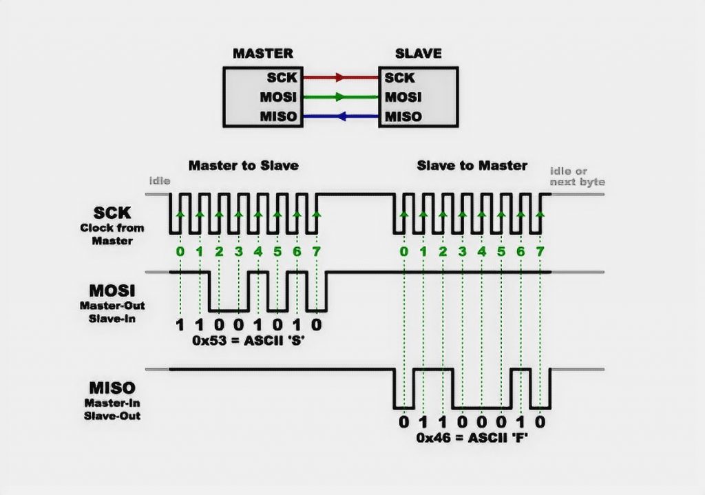
How To Use Spi On Arduino Easy Guide Nerdytechy
Flash Memory Controllers 227.

. FPGA Implementation of SPI Bus Communication Based on State Machine Method The SPI bus is a. Today we will introduce the Inter IC I2C protocol. We will examine the I2C protocol from the lowest level of abstraction the electrical interface up to the most complex which is the.
HPS Block Diagram 222. The below I2C protocol timing diagram gives a clear idea of the working of the protocol. PIN Diagram of I2C Slave The desired slave pulls the SDA line LOW to send ACK signal.
Depending on RW bit value either master or slave sends the 8-bit. This is a serial communication protocol that can connect low-speed devices. Introduction to STM32 I2C peripherals STM32s I2C peripherals.
I noticed that the timing diagrams for i2c block read and SMBus block read dont exactly line up right. Scan Manager Address Map and Register Definitions. Detailed information about the architecture of the I2C module is in Section 2.
The DS1307 is a low power Full Binary BCD Real Time Clock RTC IC with 56 bytes of SVRAM that communicates through I2C Protocol. Introduction to I2C peripherals of STM32 STM32s I2C. Pin Diagram of I2C Slave.
This way of processing the I2C protocol by hardware peripherals reduces the work of the CPU and makes software design easier. I2C is a Multi-point protocol in which a maximum up-to 128 peripheral devices can be connected to communicate along the serial interface which is composed of a bi-directional line SDA and. DS1307 Pin Diagram.
SCL and SDA are connected to a positive supply through pull-up. I2C Protocol Programming in C for 8051 Interfacing of I2C protocol EEPROM with. The clock frequency range of the SPI protocol is a maximum of 500 kHz.
I2C Primer is the. I2C protocol uses a two-wire interface for bidirectional communications between the devices connected to the bus. I2C or Inter-Integrated Circuit is a commonly used serial communication protocol in establishing communication between devices especially for two or more different circuits.
It is a master-slave. Download scientific diagram SPI bus protocol model block diagram from publication. This way of processing the I2C protocol by the hardware peripherals reduces the work of the CPU and makes the software design easier.
Problem is theres no way to even retrieve those missing bytes without. 13 Functional Block Diagram A block diagram of the I2C module is shown in Figure 1. I2C stands for the inter-integrated controller.
SPI Protocol Block Diagram Serial Peripheral Interface Specifications The specifications are.

Circuit Diagram Of I2c Communication With Pic Microcontroller Pic Microcontroller Microcontrollers Wearable Electronics

Lpg Gas Leakage Detector Using Arduino Gas Detector Arduino Electronics Projects Diy

Pcf8575 I2c 16 Pins Digital I O Expander Fast Easy Usage Arduino Esp8266 And Esp32 Arduino Address Map Digital

Pin On Arduino Web
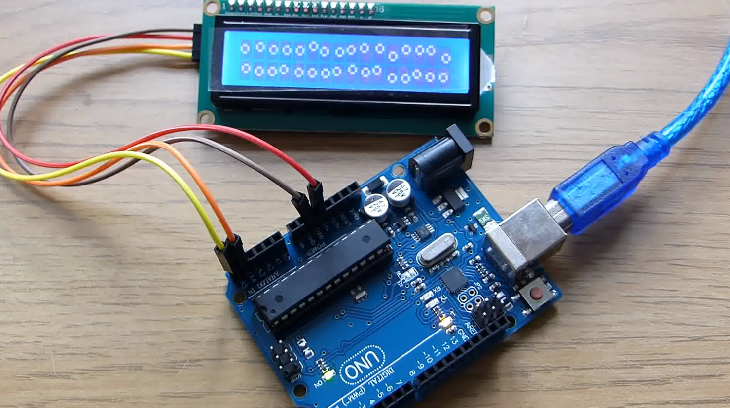
Arduino Lcd I2c Tutorial For Beginners Nerdytechy
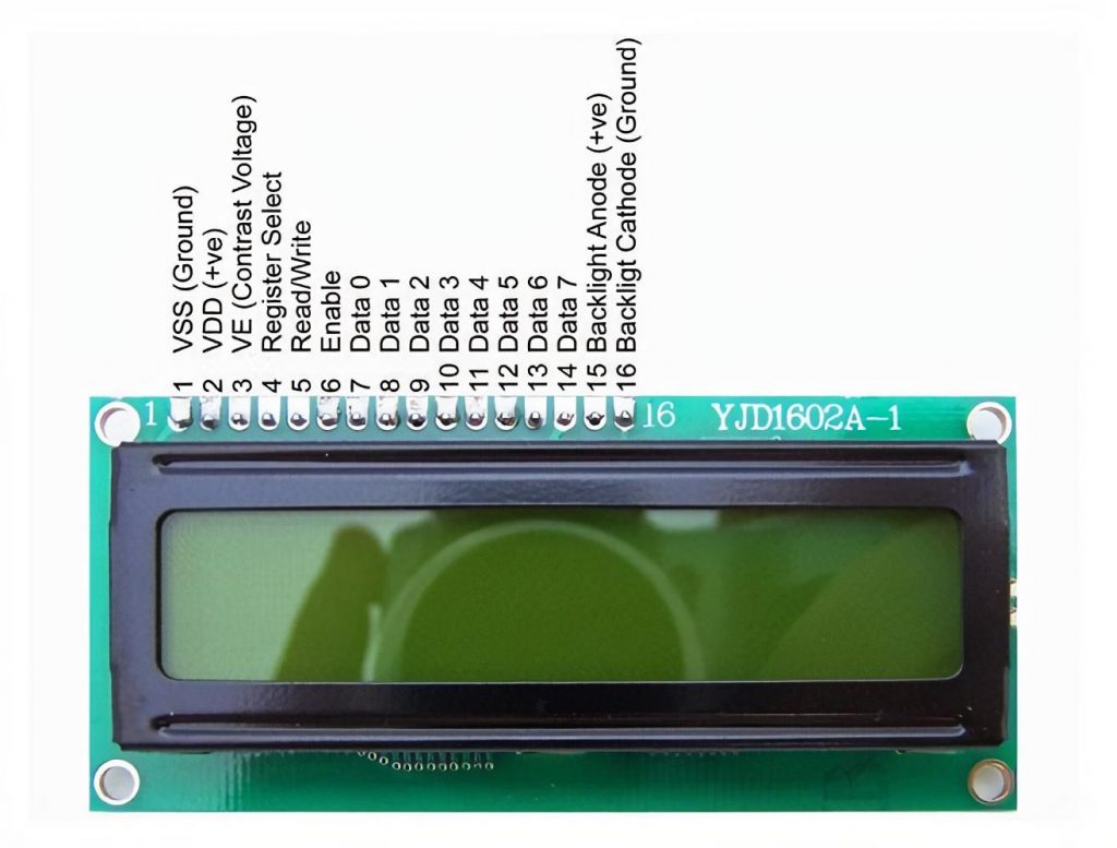
Arduino Lcd I2c Tutorial For Beginners Nerdytechy

Pin On Arduino

Pin On Electronics

Simple Bus Level Shift I2c Mosfet Level Converter Fairchild Bss138 Schematic Electronics Circuit Circuit Application Note

Pin On Atmega328 Analogue I O Port Expander Using I2c Bus

Pin On Schematics
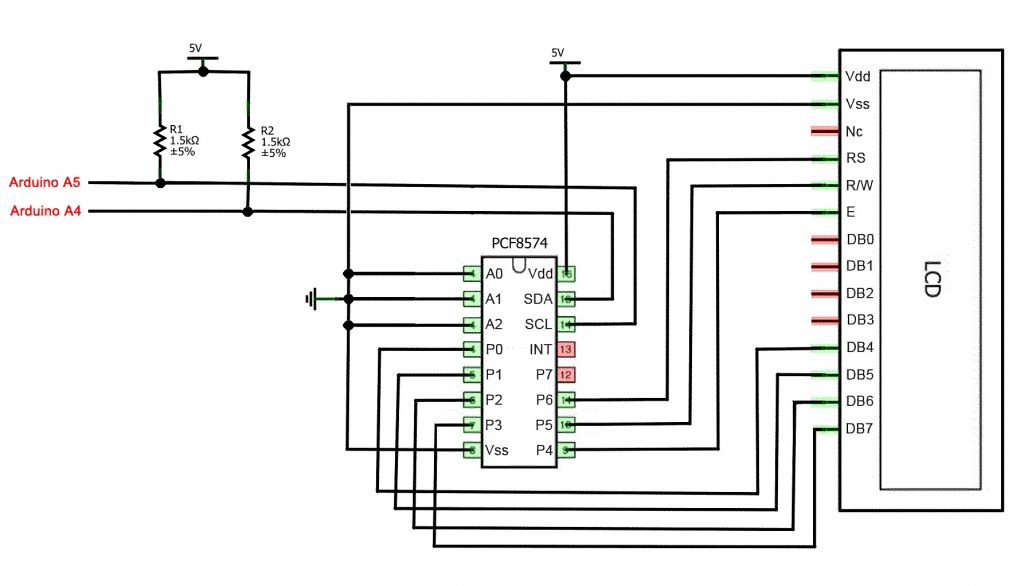
Arduino Lcd I2c Tutorial For Beginners Nerdytechy

Building Internet Of Things Using Attiny2313 Visit Http Xanthium In Buy Rs485 Modbus Controlled 6 Chan Circuit Board Design Electronic Circuit Projects Relay

Unique Reading Schematic Diagrams Diagram Wiringdiagram Diagramming Diagramm Visuals Visualisation Graphical Check More At Ht Bus System Arduino Circuit
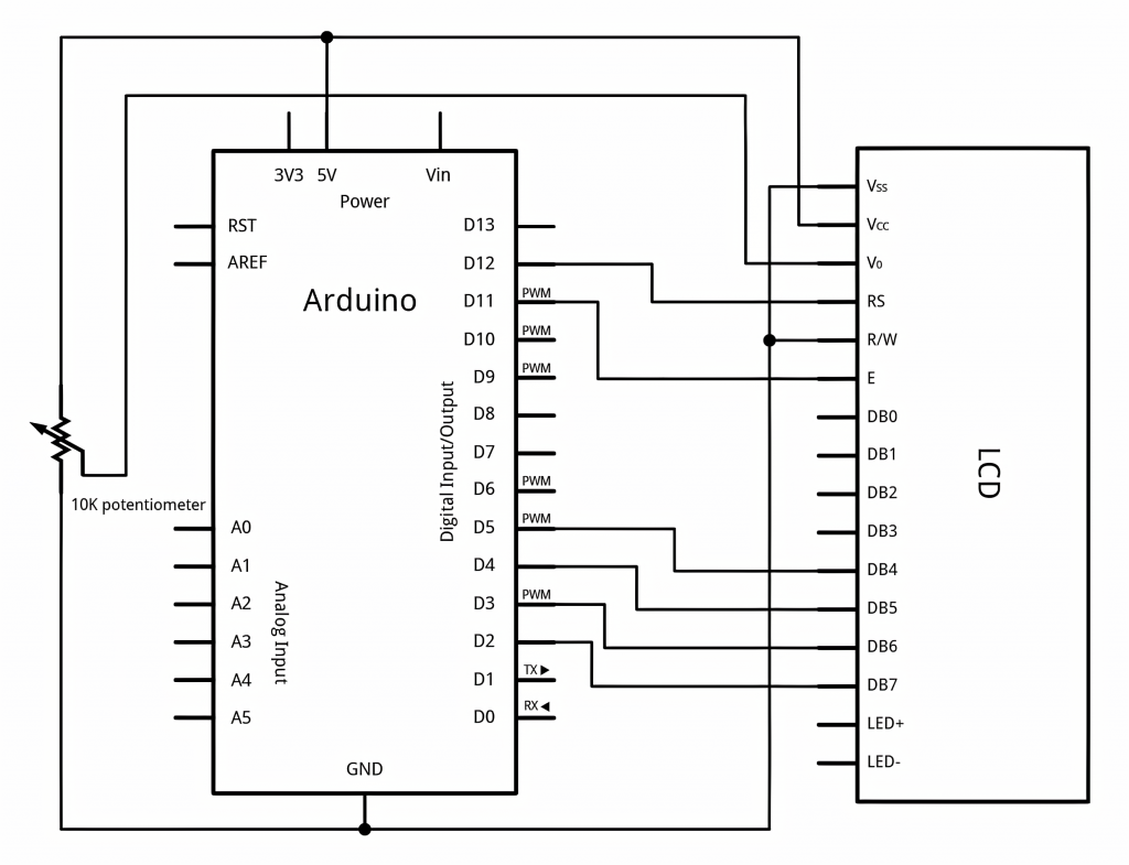
Arduino Lcd I2c Tutorial For Beginners Nerdytechy

Pin On Avr Tutorial Projects

Pin On Elektronika